Inhaltsverzeichnis
Raspberry Pi ZERO USB Hub Case / Housing
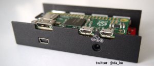
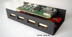
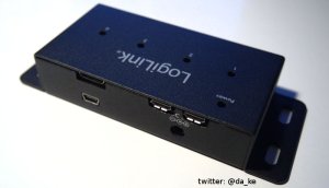
This is my take on a Raspberry Pi ZERO build into a USB hub. It has be done before and i don't take credit for the initial idea. Some other projects take out the USB hub pcb, piggybacking the Raspberry Pi ZERO onto it and redesig a new case around it. For this build i reused the existing case of the USB hub and fitting everything in it.
Preview of the final result:
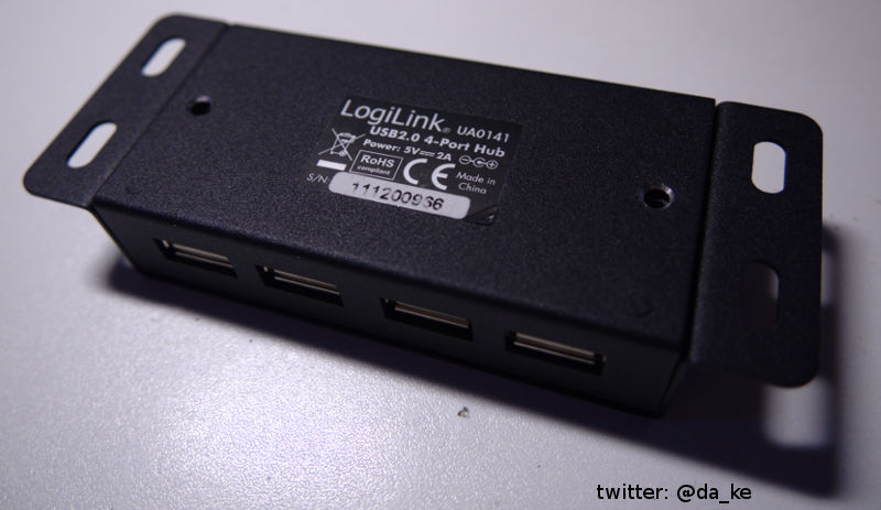
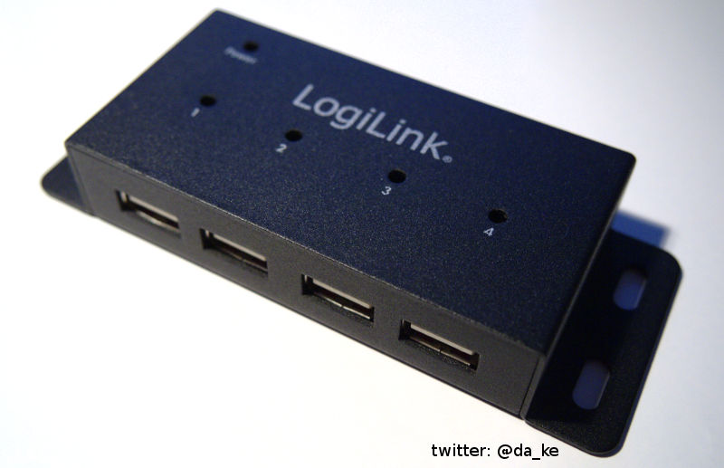
LogiLink USB Hub UA0141
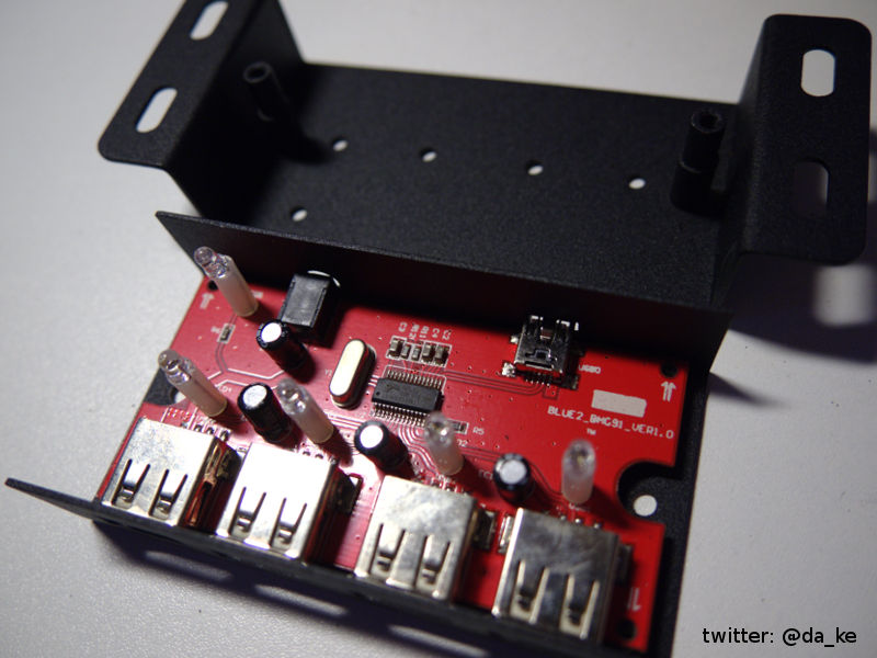
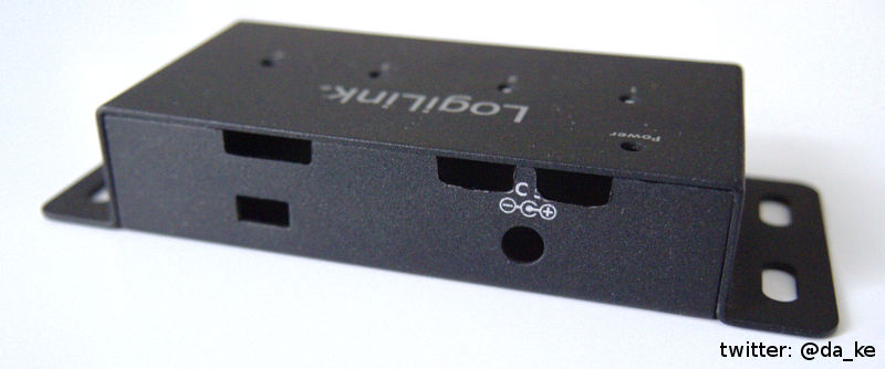
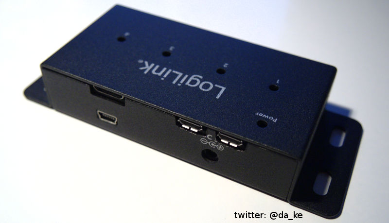
The LogiLink UA0141 is a 4 port USB 2.0 Hub with a full metal case and mounting flanges on the side.
After removing the two screws at the bottom you can open the case. It's not the best electrical design and has no protection fuses at all. This USB hub also backfeed power to the connected computer and if you don't connect the external power supply to the hub it could eventually overload the USB port of the connected host computer. It's not a good design but for the Raspberry Pi ZERO modification it's fine. We want to backfeed power from the hub to the Raspberry Pi.
Remove the 4 screws holding the main pcb to remove it from the case.
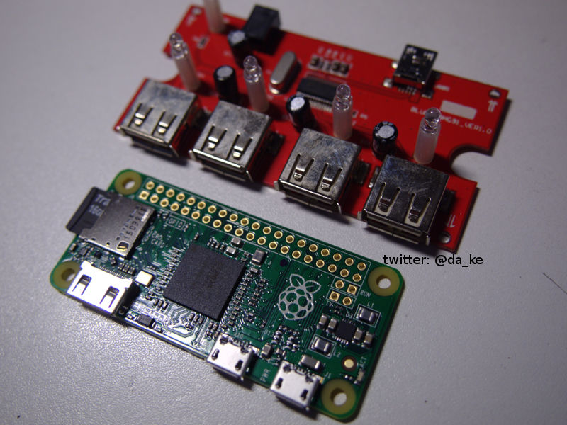
Size comparison of the USB hub pcb and the Raspberry Pi ZERO. It's a perfect match and as we can see later it fits perfectly in the metal case of the USB hub.
Modifications and electrical connections
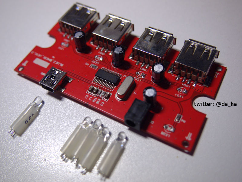
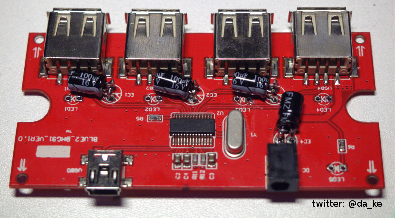
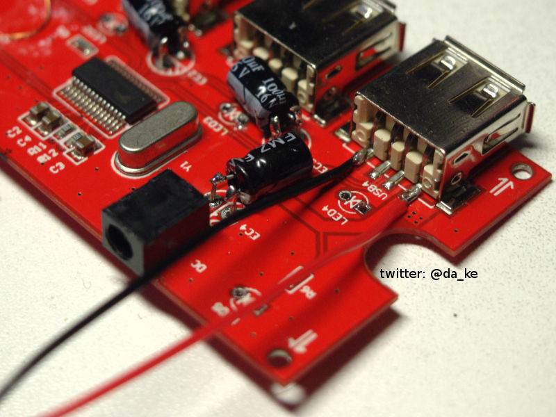
To make space for the Pi ZERO we need to desolder the indicator LEDs and rotate the electrolytic caps to mount them flat to the pcb. If you want you could reconnect the LEDs later or relocate them. The blue status LEDs for the USB ports are very bright and i don't need them. They light up if you connect anything to the port and are kind of pointless. It's not a indicator light if the device is recognized or functioning at all.
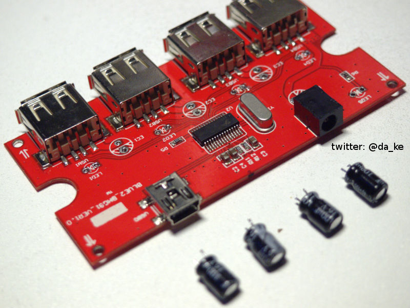
The 4 electrolytic caps (100uF / 16V) are to tall and in the way of mounting the Pi ZERO. They need to be replaced by new caps with a smaller body or rotated by 90° flat to the pcb.
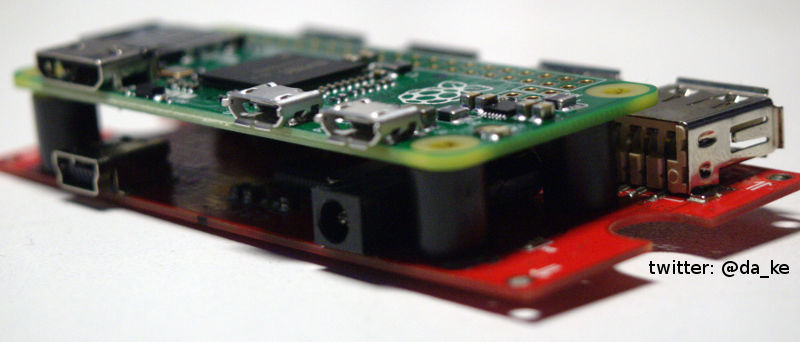
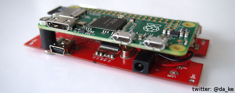
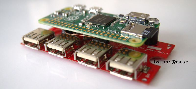
After removing the parts the Pi ZERO can be fitted above the hub pcb. This image shows how it can be placed with 10mm to 12mm spacers.
Now solder in 4 new 100uf / 16V capacitators flat to the pcb or reuse the old desoldered caps. You might have to use short pieces of copper wire cause the old component leads are cut too short. All components have to be lower than the four USB sockets! Otherwise you will have problems fitting everything back in the case.
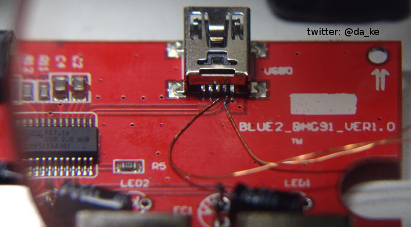
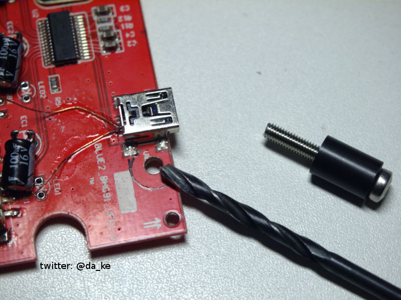
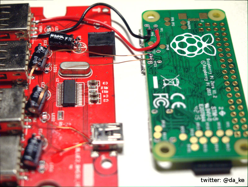
Use very thin magnet wire to connect the data lines of the usb hub to the Pi ZERO. Magnet wire is copper wire with a thin layer of insulation. Coat the ends of the magnet wire first. Remove the insulation at the end of the wire you want to solder to the socket pins. Put some solder on the tip of your soldering iron and hold the magnet wire in the liquid solder until the insulation is burned away and the tin sticks to the magnet wire. You can identify the data lines easily because they are the only two pcb traces directly connected to the black IC to the left. Use a thin solder tip and „no clean flux“ / soldering flux pen.
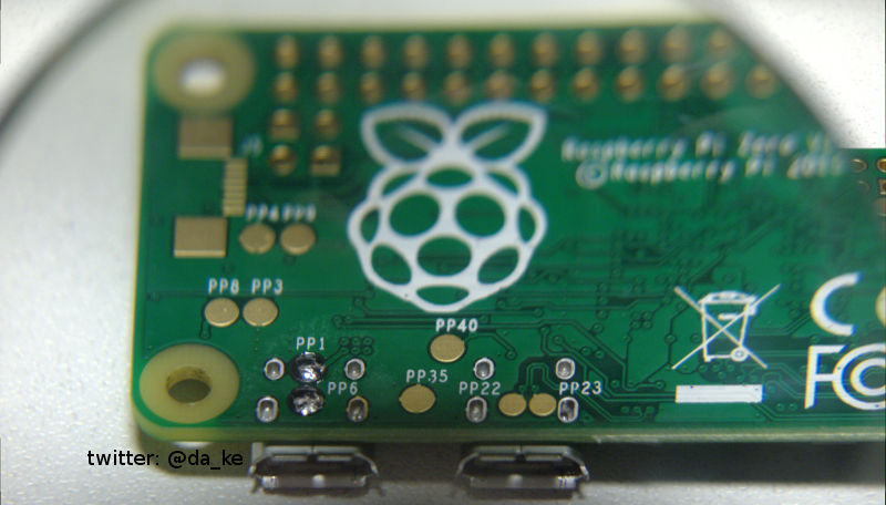
The Raspberry Pi ZERO has test points you can use to connect the wires from the USB hub to. A list of test points and their function you can find on this site http://hackers.gallery/841/misc/raspberry-pi-zero-pad-probing.
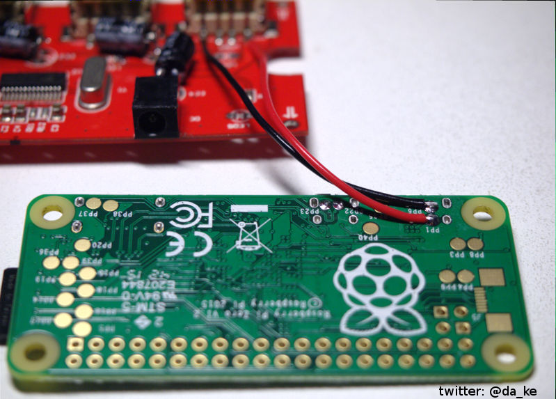
For power we need test points PP1 (5V) and PP6 (GND).
For the usb data lines we need PP22 (USB D+) and PP23 (USB D-).
To power the Pi ZERO you can connect two wires (+5V and GND) anywhere to the main power rail of the USB hub. All USB ports are directly connected to the power socket of the hub.
Now we need a hole in the USB hub pcb to mount the Pi ZERO with a 12mm spacer and a 3mm diameter screw. Make sure to mark the exact position first and take care not to destroy any traces on both sides of the USB hub pcb! Check the top and bottom side for clearance! Drill the hole with a 3mm drillbit. Use a proxxon minidrill (or a dremel) and carefully drill the hole.
Here you can see a overview of all 4 connections made between the Raspberry Pi ZERO and the USB hub (power and USB data lines).
Case modifications
Read this steps carefully and measure twice!
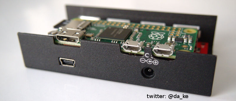
Now we need cutouts for the HDMI and USB ports of the Pi ZERO. To mark the positions for the cutouts place the whole assembly (USB hub pcb and Pi Zero on top) in the case. Now mark the width and position for each cutout on the case.
I don't give you exact measurement for this cutout cause you have to match it to your exact mounting position of the Raspberry Pi ZERO! Take care that you can close the lid as well! And insert the memory card to the Pi ZERO cause it sticks out of the side a bit and needs some additional space!
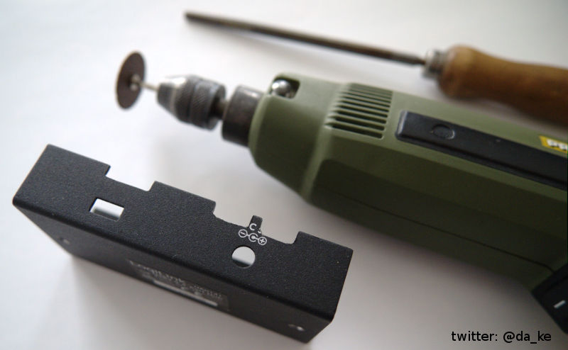
I used my proxxon minidrill and a cutting wheel. Use proper eye protection cause there will be dust, metal particles and the cutting wheel breaks very easily as well! Be warned, it's dangerous for your eyes!
After cutting out the slots use a small file to smooth the edges.
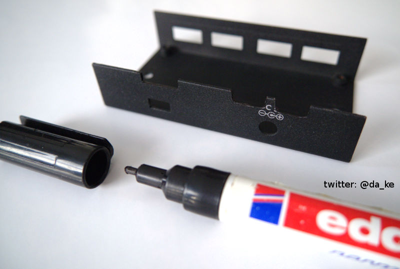
For the look apply some makeup and paint the metal black with a sharpie.
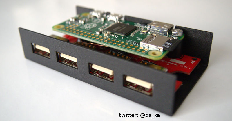
This is how it should look like after the job is done.
Final assembly
Mount the Raspberry Pi ZERO on top of the USB hub pcb using the spacer and a 3mm screw. I had to cut the screw to size cause the standard length did not fit (dremel and cutting wheel). Take care all 4 wires between the two are aligned ok.
Back side view of the assembly:
Front side view of the assembly:
Now place the assembly into the case. It's a fiddly job but it works. Don't use too much force, bend the case sides a bit outwards if you need to.
Back side view:
Front side view:
Now close the top and insert the two screws at the bottom.
You are done! Now you have a fully functional mini computer in a USB hub. Connect a HDMI cable, keyboard, mouse and optional a wifi stick or USB ethernet card and enjoy your Raspberry Pi ZERO.
Future Improvements
You can make a additional cutout at the top of the case for the GPIO port. With a optional header you could connect a ribbon cable directly to the Raspberry Pi ZERO to interface other hardware like sensors or a arduino board.

